A full CNC back gauge retrofit can run $10,000 to $25,000 or more, depending on axes and complexity. For low-volume shops doing simple single-flange work, that's a hard number to justify. Building a backstop around a linear actuator looks like an obvious middle ground.
It can work. But results swing wildly based on actuator selection, mounting rigidity, feedback control, and calibration. This guide walks through the build, the parts list, the parameters that actually matter, and the point where a DIY rig stops making sense.
Key Takeaways
- Adds automated X-axis positioning to manual brakes at a fraction of CNC cost
- Success hinges on matching actuator thrust/stroke to load and adding closed-loop feedback
- This build fits low-to-medium volume shops running simple, single-flange parts
- Skipping rigid mounting or position feedback is the top cause of drift
- Multi-axis needs or high-volume production still favor a factory CNC back gauge
How to Build a Press Brake Backstop Using a Linear Actuator
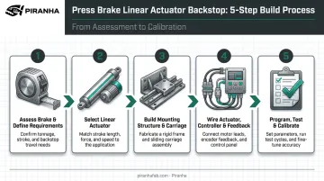
Step 1: Assess Your Press Brake and Define Requirements
Before ordering any hardware, look at what you're actually working with.
- Check rear clearance: confirm existing mounting points on the frame or bed, and verify enough space behind the brake for the actuator's full stroke
- Calculate travel distance based on your longest flange length, adding margin for setup and material handling
- Define your tolerance target: what repeatability do your parts actually need? A ±0.010 in. tolerance calls for very different hardware than ±0.030 in.
Skipping this step means guessing at every purchase that follows.
Step 2: Select the Right Linear Actuator
This is where most DIY builds succeed or fail.
Drive type comparison:
| Drive Type | Accuracy | Cost | Best For |
|---|---|---|---|
| Ball-screw electric | Highest | $$$ | Repeatable, tight-tolerance work |
| Belt-driven electric | Moderate | $$ | Faster travel, moderate precision |
| Pneumatic cylinder | Lowest | $ | Budget builds, loose tolerances |
Ball-screw actuators generally deliver tighter positioning than belt or pneumatic options because lead accuracy and backlash are more tightly controlled. Backlash, structure, and feedback quality still affect the final number, not the screw alone.
Beyond drive type, size the actuator to your actual load:
- Thrust must cover acceleration force, friction, and breakaway force combined, not just the static carriage weight
- Stroke lengthshould exceed your calculated X-axis travel by a safety margin, rather than match it exactly
- IP rating should match shop conditions: dusty metal shops with coolant spray call for at least IP54, and grinding or heavy dust environments push that up to IP65, according to Tolomatic's manufacturing guide on IP ratings
Skip the temptation to apply a generic 2:1 safety margin borrowed from pneumatic sizing rules. Electric actuators need their own calculated static and dynamic load numbers, checked against peak and continuous ratings.
Step 3: Build the Mounting Structure and Carriage
An actuator alone doesn't guide anything laterally. That's the guide rail's job.
- Design a rigid carriage and stop-finger bracket riding on linear guide rails mounted parallel to the actuator, so contact force from sheet metal doesn't rack the carriage
- Use a datum rail as your reference surface, align the subsidiary rail with a straightedge or dial indicator, and torque bolts sequentially per the rail manufacturer's spec
- Reinforce the frame connection point: repeated sheet-metal impacts loosen weak brackets fast, and a mount that's solid on day one can work loose within weeks of production use
Wider guide spacing and four-row guide blocks improve resistance to the overhung moment created when material pushes against the stop finger off-center from the actuator's centerline.
Step 4: Wire the Actuator, Controller, and Feedback System
This step turns a motorized ram into an actual positioning system.
- Pair the actuator with a compatible driver: stepper for lower-cost builds, servo for tighter control
- Add position feedback: an encoder or linear potentiometer closes the loop so the controller knows the actual position, not just the commanded one
- Install limit switches at both travel extremes to prevent overtravel damage
- Wire an E-stop and safety interlock consistent with ANSI B11.3 press brake safety guidance, which governs point-of-operation hazards, control systems, and emergency-stop functionality on power press brakes
Don't treat feedback as optional. Open-loop control (stepper with no encoder) drifts the moment the actuator loses even one step under load, and you won't know until the parts come out wrong.
Step 5: Program, Test, and Calibrate
Rushing this step wastes everything built in Steps 1 through 4.
- Run unloaded test cycles first: confirm smooth travel, correct homing, and no binding before any material contact
- Calibrate zero position against the die centerline using gauge blocks
- Perform test bends and compare actual flange length against programmed value
- Adjust the offset until real parts match your target, then run a batch of 10-20 to confirm the number holds
Encoder resolution and screw lead accuracy set the ceiling on how tight you can hold tolerance. Calibration is what determines whether you actually hit that ceiling in practice.
When Should You Build a Backstop Using a Linear Actuator?
This isn't a universal fix. It fits specific shop profiles far better than others.
Good fit:
- Low-to-medium volume shops
- Simple, single-axis flange work
- Older manual brakes with usable rear clearance
- Moderate tolerance requirements, not aerospace-grade precision
Poor fit:
- Parts requiring multiple flange dimensions per run
- Asymmetric geometry needing independent finger positioning (Z1/Z2-style)
- Heavy plate or wide sheets requiring higher-thrust actuators and stiffer mounting than typical DIY builds provide
- High-volume production where downtime from a failed homemade rig costs more than a factory system
If your parts mix keeps changing dimensions, or your material is getting heavier, that's a signal the DIY path is about to hit its ceiling.
What You Need Before Building Your Linear Actuator Backstop
Skimping on hardware or skills is the most common reason DIY backstops fail to hold tolerance.
Equipment / System Requirements
- Linear actuator sized to your calculated thrust and stroke
- Compatible motor driver/controller
- Linear guide rails or bearings (separate from the actuator's own rod or screw)
- Regulated power supply matched to the driver's specs
Skill, Safety, and Compliance Readiness
- Basic electrical wiring and controls programming ability
- Lockout/tagout procedure knowledge before working near the brake
- Familiarity with press brake safety standards before wiring any motion system near the point of operation
- Awareness that the rear back gauge area remains inside the guarded workspace, not a safe zone to improvise in
Key Parameters That Affect Accuracy and Performance
A backstop's real-world performance hinges on a handful of controllable variables, not just the number on the actuator's spec sheet.
Thrust / Load Capacity
Insufficient thrust causes stalling or lost steps when pushing against sheet metal friction. Undersized actuators produce inconsistent flange lengths as load increases across a batch. The first few parts might be fine, but part 40 drifts off.
Positioning Accuracy and Repeatability
Ball-screw lead accuracy and encoder resolution set the ceiling on achievable tolerance. But resolution isn't accuracy: a sensor can report movement in fine increments while the whole axis still deviates from true position due to guide compliance, screw error, or calibration drift.
Travel Speed and Acceleration
Excessive speed or acceleration causes overshoot or vibration in a lightweight DIY carriage. Tuning the speed and acceleration curve down reduces cycle time waste without sacrificing final position accuracy. Running at maximum speed rarely produces the best result on a lightweight frame.
Duty Cycle and Environmental Rating
Shop dust, coolant spray, and thermal cycling shorten actuator life fast if the IP rating doesn't match conditions. Running an actuator rated for intermittent duty in a high-repetition production role is a common mismatch that leads to premature motor burnout.
Common Mistakes and Troubleshooting
Most DIY backstop failures trace back to a small set of recurring errors.
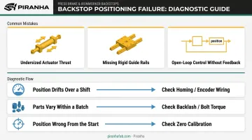
Common Mistakes:
- Undersizing actuator thrust for the actual backgauge load, causing stalls or skipped steps
- Skipping rigid guide rails, letting the carriage rack and the stop finger drift out of alignment under contact force
- Running open-loop control with no encoder feedback, allowing gradual position drift nobody catches until parts fail inspection
Catching these mistakes early prevents most drift issues. When symptoms still appear, the table below narrows down the cause fast.
Troubleshooting Drift or Inconsistent Flange Lengths:
| Symptom | Likely Cause | What to Check |
|---|---|---|
| Position drifts over a shift | Lost home reference or failed feedback | Homing routine, encoder wiring |
| Parts vary within one batch | Backlash or loose mounting | Screw/belt backlash, bolt torque |
| Position wrong from the start | Bad zero calibration | Re-run zero calibration against gauge blocks |
Start with the homing routine and encoder wiring first — that's the fastest fix for the most common failure mode.
When to Upgrade to a Factory CNC Back Gauge Instead
A DIY linear actuator backstop has real limits. Once your shop's needs outgrow single-axis control, a purpose-built CNC back gauge delivers better return than maintaining a homemade rig.
That upgrade point typically shows up as:
- Multi-axis positioning needs, such as R-axis tilt or independent Z1/Z2 finger control
- Part complexity that exceeds what a single-axis actuator can reliably hold
- Production volume high enough that manual resets slow the line
- Compliance requirements that call for documented, repeatable positioning
Retrofit economics support this shift. Control-only retrofits have run $10,000 to $25,000 depending on complexity, with single-axis systems sometimes under $10,000. That number starts looking reasonable against the labor cost of maintaining, troubleshooting, and recalibrating a DIY rig indefinitely.
This is where a factory-engineered option earns its keep. Piranha builds hydraulic press brakes as part of a full fabrication lineup, including laser, press brake, shear, plate roll, and ironworker systems, backed by U.S.-based service and same-day parts shipping from Belvidere, Illinois.
Instead of sourcing an encoder here and a driver there, you're working with one vendor for the whole machine.
Scalable automation on a factory press brake also means you're not staring down a full machine replacement every time production volume or part complexity grows. That's the tradeoff a self-built system can't fully match: it solves today's job, but it doesn't scale the way a factory-engineered machine does.
Frequently Asked Questions
What type of linear actuator is best for a press brake backstop?
Ball-screw electric actuators offer the best balance of accuracy and repeatability for backstop applications. Belt-driven or pneumatic options suit lower-precision, budget-focused builds where tight tolerance isn't critical.
How much thrust does a press brake backgauge actuator need?
Required thrust depends on carriage weight, friction, and sheet contact force combined — not just static weight. Size with a safety margin above your calculated static load to avoid stalling under real production conditions.
Can I retrofit a manual press brake with a linear actuator backstop?
Most manual press brakes with adequate rear frame clearance can be retrofitted. Success depends on matching the actuator, mounting structure, and controls to your machine's size and load requirements.
What accuracy can I realistically expect from a DIY linear actuator backgauge?
DIY builds typically fall short of factory CNC servo repeatability. They're best suited for parts with moderate tolerance requirements, not precision aerospace-grade work.
Is it safe to build my own press brake backstop?
Safety is achievable with proper limit switches, E-stop interlocks, and adherence to ANSI B11.3 guidelines. Improper wiring or mounting near the point of operation introduces real operator risk.
When should I stop building and just buy a factory back gauge system?
Upgrade once part complexity, production volume, or compliance tolerances exceed what a single-axis DIY actuator can reliably deliver. Factory systems reduce downtime and long-term maintenance burden.